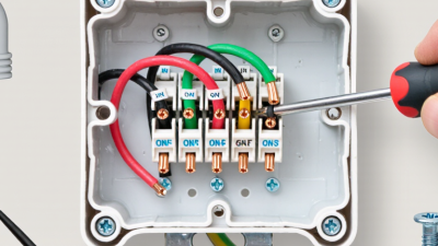
How to Wire a Push Button On Off Switch?
Wiring a Push Button On Off switch looks simple, but a small mistake can damage equipment or create a serious electrical hazard. This guide explains the process in clear, practical steps. It focuses on identifying terminals, checking circuit ratings, and testing connections before applying power. The method works for many low-voltage projects, control panels, appliances, and automotive accessories, but the switch manufacturer’s diagram must always take priority.
Safety comes first. Disconnect the power source, verify the voltage with a suitable multimeter, and choose wire with an appropriate current rating. A typical switch may include COM, NO, and NC terminals. COM is the common connection, while NO closes the circuit when pressed. NC opens when pressed. Some buttons are momentary, while others remain latched after activation. They are not interchangeable. Read the label carefully.
A reliable installation also needs secure terminals, correct polarity, and suitable overcurrent protection. Loose strands can produce heat inside a cramped enclosure. That detail is easy to overlook. Before finishing, inspect every connection and test continuity with power removed. Then restore power briefly and watch for unusual heat, noise, or flickering. I have found that diagrams can seem obvious until the real switch has different terminal markings. Take a photo before disconnecting an existing circuit, and compare it with the datasheet. This guide may not cover every specialized system, so qualified electrical advice is appropriate when voltage, current, or equipment value is significant.
Understanding Push Button On-Off Switches and Their Terminals
How to Wire a Push Button On Off Switch?
Understanding the terminals is more important than matching wire colors. A maintained push button usually has two power terminals. One receives the positive supply, and the other sends power to the load. Pressing the button changes the internal contact and keeps the circuit on or off. Turn the power off before touching any wire. I once found a switch installed backward, simply because its terminal markings were ignored.
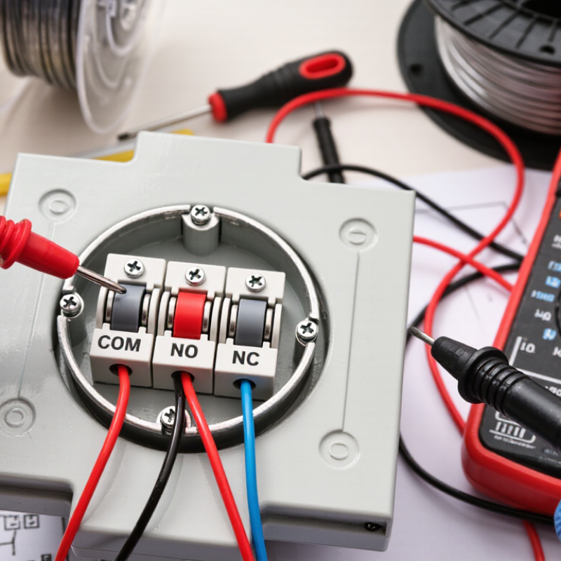
Some switches use COM, NO, and NC terminals. COM is the shared connection. NO means normally open, so the circuit closes when the button is pressed. NC means normally closed, so the circuit opens when pressed. For a momentary control, connect the supply to COM and the load or control input to NO. Use NC only when the circuit must remain active until pressing the button. Check continuity with a multimeter. Do not guess.
Illuminated switches may have extra terminals for the lamp or LED. These terminals can require correct polarity, especially on low-voltage DC circuits. A four-terminal switch may also contain separate contacts for switching two circuits. The wiring diagram remains the best reference, but diagrams can be surprisingly vague. Use a fuse suited to the circuit, secure exposed conductors, and confirm the switch rating exceeds the load. For household mains wiring, a qualified electrician should verify the connection. Small mistakes can become hot wires.
Gathering Tools, Materials, and Electrical Safety Equipment
Before wiring a push button on-off switch, prepare the work area and inspect every component. You will need the switch, correctly rated wire, wire stripper, screwdriver, terminal connectors, a multimeter, and a suitable enclosure. Keep a flashlight nearby if the panel is poorly lit. Small details matter.
Disconnect the power source completely. Then verify the circuit with a multimeter, even if the breaker appears off. Wear safety glasses and use insulated tools in good condition. Check the switch rating against the circuit voltage and expected current. A button designed for low-voltage control should not operate a high-current load directly. Choose wire with suitable insulation and a gauge approved for the application. Loose strands can cause trouble later.
Label each conductor before removing or connecting anything. Follow the switch terminal markings and the equipment wiring diagram, rather than relying on wire color alone. Secure the connections firmly, but avoid crushing the terminals. Place the switch inside a protective enclosure when exposed conductors could be touched. I once overlooked a slightly loose terminal during a practice setup; the circuit worked briefly, then became unreliable. That mistake reinforced the need for a gentle pull test and a second inspection. Recheck the enclosure, insulation, and terminal tightness before restoring power. Stop if the circuit behaves unexpectedly or if the diagram is unclear.
Identifying the Power, Load, and Ground Connections
How to Wire a Push Button On Off Switch?
Identifying each connection prevents most wiring errors. Disconnect the power source before touching any terminal. A multimeter helps confirm the switch layout. Set it to continuity mode, then press the button while testing pairs of terminals.
The power connection usually receives voltage from the supply. The load connection carries that voltage toward the lamp, motor, or other device. Look for labels such as COM, NO, and NC. COM is often the incoming power terminal. NO closes only when the button is pressed. NC opens when the button is pressed.
Ground requires more care. In a low-voltage DC circuit, ground commonly means the negative return path. In many AC systems, protective ground connects to the metal enclosure instead. It should not normally carry the operating current.
Never assume that green, black, or red wires have the same meaning in every installation. Wire colors can vary between systems. Check the equipment diagram and measure voltage with suitable test equipment.
A switch rating must match the load’s voltage and current. Motors may draw a sharp starting current. That detail is easy to miss. For an illuminated switch, extra terminals may power the internal lamp, so the basic COM and NO test may not explain everything.
I would label each wire before removal and photograph the original layout. Still, photographs can mislead when terminals look identical. Test again after wiring, inspect for loose strands, and use an enclosure that prevents accidental contact. Restarting power should be the final hands-off step.
Wiring the Switch in a Basic On-Off Circuit
How to Wire a Push Button On-Off Switch?
Wiring the Switch in a Basic On-Off Circuit
A latching push button can control a basic on-off circuit by opening or closing the live conductor. Connect the power source’s live wire to the switch input terminal. Connect the output terminal to the load’s live terminal. The load’s return wire connects directly to neutral or the negative supply terminal. For low-voltage DC projects, connect positive through the switch and connect negative directly to the load. Always confirm the terminal markings before wiring. Some push buttons are momentary, not latching, so they will not maintain power after release. I have seen this mistake during quick bench tests.
Choose a switch with a voltage and current rating above the circuit’s measured load. Motors and lamps can create starting surges. The NFPA report Home Fires Involving Electrical Distribution and Lighting Equipment estimated about 32,000 related home fires annually in the United States during 2015–2019. Poor connections, damaged conductors, and overloaded components remain practical hazards. Use insulated terminals, secure strain relief, and an enclosure that prevents accidental contact. Disconnect all power before changing wiring. For mains-voltage circuits, local electrical rules and a qualified electrician matter more than a simple diagram.
Tips: Test continuity with power disconnected. Label the input and output wires. Tighten terminals gently. Do not rely on wire color alone. I still recheck polarity and load current, because a neat circuit can hide one wrong connection.
Testing the Circuit and Troubleshooting Common Wiring Problems
When testing a push button on-off switch, disconnect power before touching any terminal. Inspect the wiring carefully. Loose strands, damaged insulation, or a poorly tightened screw can create misleading results. Confirm the switch type, because a latching switch should remain on after pressing it. A momentary switch should not.
Set a multimeter to continuity mode. With the button released, check the expected terminals. The meter should show continuity only when the switch is in its closed position. Press the button several times and listen for a steady beep. An unstable reading may indicate worn contacts or a loose connection. Restore low-voltage power only after checking the circuit. Test the load separately if it still does not operate.
A common problem is connecting the supply wire to the wrong terminal. The switch may click normally, yet the circuit remains open. Another fault appears when neutral and control wires are confused. Trace each wire from its source to its load, rather than trusting color alone. I once blamed the switch, but the real fault was a crimp that looked secure and pulled free gently. That mistake changed my testing routine. I now tug each finished connection lightly and measure voltage at both sides of the switch. For household mains circuits, use a qualified electrician and the applicable local requirements.