Wiring a Push Button On Off Switch looks simple, but a small mistake can create heat, arcing, or an unexpected start. The risk is real. NFPA’s Home Electrical Fires report estimates that U.S. fire departments responded to about 32,950 home fires involving electrical distribution and lighting equipment annually from 2016 to 2020. These fires caused approximately 470 deaths, 1,100 injuries, and $1.3 billion in property damage. The switch may be small. The consequences are not.
This guide explains safe wiring through practical checks and recognized industry principles. A correctly selected switch must match the circuit’s voltage, current, load type, and duty cycle. Motor and inductive loads deserve extra caution because their starting current can exceed normal operating current. UL 61058-1 addresses requirements for switches used in appliances, while NFPA 70, the National Electrical Code, provides broader installation guidance. These standards do not replace local requirements or a qualified electrician’s judgment.
Before touching a conductor, disconnect the supply and verify isolation with a properly rated tester. Do not trust a dark indicator or a silent machine. Inspect insulation, terminals, strain relief, enclosure clearance, and grounding continuity. A tidy wire route can still hide a loose terminal. That is where this topic becomes less comfortable: diagrams often appear perfect, yet real installations contain aging cables, mislabeled conductors, and unsuitable switches. If the circuit controls a high-current, wet-location, or safety-critical load, professional inspection is the safer decision. Small patience prevents large failures.
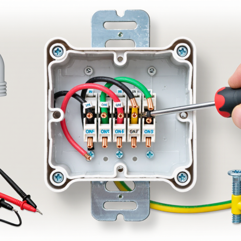
Identify the push button switch type before connecting any wire. A momentary switch changes state only while pressed. A maintained switch stays on or off after release. This difference affects the entire circuit. Check the switch body, datasheet, and rated voltage carefully. Do not trust color alone.
Look for terminal markings such as COM, NO, and NC. COM is the common connection. NO means normally open, while NC means normally closed. A two-terminal switch usually uses COM and NO for a simple control circuit. A three-terminal switch may support either normally open or normally closed operation. With power fully isolated, use a continuity tester to confirm each terminal. In practical bench testing, this small check has prevented several wiring mistakes. I once assumed two similar terminals were interchangeable. They were not.
Tips: Photograph the original wiring before removal, but do not copy it blindly. Confirm the circuit diagram. Use wire sizes and connectors suitable for the load. Secure every terminal so no copper strands remain exposed. For mains-powered equipment, install proper protection and ask a qualified electrician to verify the work. Test the switch with low voltage first when possible. Keep the enclosure closed during operation. A switch can feel solid and still be incorrectly rated. Safety labels help, but careful measurement is more reliable.
Turn off power before touching the switch, even for a quick replacement. A breaker label is not proof. Labels can be outdated or wrong. Switch off the correct circuit, then verify voltage with a tested meter. Check the meter on a known live source before testing. Check it again afterward. This simple habit reduces dangerous assumptions.
Prepare a clean, dry wiring area before removing the old switch. Keep loose metal objects away from the box. Photograph the existing connections, then label line, load, neutral, and ground wires. Do not rely on wire color alone. Inspect insulation for cracks, heat marks, or brittle sections. According to the National Fire Protection Association’s report covering 2016–2020, electrical distribution and lighting equipment caused about 32,000 U.S. home fires annually. These fires caused roughly 470 deaths and 1,100 injuries each year. Safe preparation matters. If the circuit remains energized, damaged, or confusing, stop and contact a qualified electrician. OSHA guidance also emphasizes de-energizing equipment before electrical work.
Tips: Use insulated tools and keep your hands dry. Confirm the switch rating matches the circuit. Leave enough wire for careful reconnection. Do not force crowded wires into the box. I sometimes find the preparation takes longer than the wiring itself. That is acceptable. A rushed connection may hide a loose terminal, and one missed detail can become a serious fault.
How to Wire a Push Button On Off Switch Safely?
Connect the wires to the correct switch terminals, not simply to the nearest screws. Turn off the power and verify the circuit is dead with a properly rated tester. For household voltage, a licensed electrician should complete the work. Low-voltage projects still need careful inspection.
Most switches label their terminals as COM, NO, and NC. Connect the incoming live wire to COM. Connect the outgoing load wire to NO when the circuit should operate after pressing the button. Use NC only when the circuit must remain closed in its normal position. Never guess the terminal layout. Check the switch diagram and test continuity before applying power.
A push button may be momentary or maintained. They are not interchangeable. A momentary switch returns when released, while a maintained switch stays in position. I have seen wiring fail because this difference was overlooked. Keep exposed copper short, tighten terminals firmly, and add strain relief where the cable enters the enclosure. Connect protective earth to the enclosure when required. Neutral wiring depends on the circuit design and should not be routed through an unsuitable terminal. Stop if the labels are unclear. Recheck every connection.
This chart shows the contact behavior of a standard SPDT push-button switch. When the button is released, COM is connected to NC; when the button is pressed, COM is connected to NO. Always turn off and isolate the power before wiring, identify the terminal markings, and verify continuity with a multimeter. For a simple two-terminal SPST switch, connect the circuit wires only to the two terminals marked for the switch contacts.
Wiring a push button on-off switch safely begins with control, not speed. Turn off the circuit at the breaker, then verify dead voltage with a tested meter. Do not trust the switch position alone. The National Fire Protection Association reported that electrical distribution and lighting equipment appeared in 32% of U.S. home structure fires from 2015 to 2019. A loose connection can create heat quietly.
Secure the switch firmly inside the correct enclosure. It should not wobble when pressed. Keep the cable jacket inside the enclosure, and use strain relief where required. Strip only the needed insulation length. Exposed copper should not extend beyond the terminal. Match each conductor with the wiring diagram, and tighten terminals to the specified torque. A connection that feels tight may still be unreliable. I recheck each terminal after arranging the wires, because wire movement can loosen a rushed connection.
Inspect every joint for damaged insulation, stray strands, and reversed conductors. Use a continuity test only after power is isolated. Then restore power carefully and check for heat, buzzing, flickering, or a burning smell. The Electrical Safety Foundation International reports that hundreds of workplace electrical fatalities occur in the United States each year, with many incidents linked to unsafe contact or faulty equipment. That figure is a reminder, not a substitute for judgment. If the circuit is unfamiliar, stop and ask a qualified electrician. A neat switch can still hide a dangerous mistake.
After wiring a push-button on-off switch, restoring power requires patience, not confidence. Turn every control to the off position, reinstall the cover, and keep hands clear of exposed conductors. The U.S. Consumer Product Safety Commission reports that electrical distribution problems remain a major source of residential fire hazards. A loose terminal can create heat silently.
Stand to the side of the panel when resetting the breaker. Then press the button once and observe the connected equipment. It should start cleanly, without buzzing, flickering, burning smells, or delayed response. Press it again and confirm complete shutdown. Use a rated multimeter to verify voltage only when you are trained to do so. OSHA treats exposed live parts at 50 volts or more as a serious electrical hazard. If the switch feels warm, trips the breaker, or behaves inconsistently, disconnect power immediately. I have learned that “almost correct” wiring is still unsafe.
Tips: Photograph the original connections before removal. Check that each conductor is fully inserted and firmly tightened. Do not rely on wire color alone; identify line and load with a tester. Test the button several times, but avoid repeated cycling under heavy load. NFPA research consistently links faulty wiring and electrical equipment to thousands of U.S. home fires each year. When the circuit layout is unclear, stop and contact a qualified electrician. A second inspection may feel excessive, but it can reveal one overlooked strand or loose screw.
| Step | Task or Data Dimension | Recommended Action | Expected Result | Safety Check |
|---|---|---|---|---|
| 1 | Confirm the switch type | Verify whether the push button is a maintained ON/OFF switch or a momentary push button. Check the terminal labels and electrical rating before wiring. | The switch function and terminal arrangement match the intended circuit. | Do not use a momentary switch where a maintained ON/OFF function is required. |
| 2 | Disconnect the power | Turn off the circuit breaker or unplug the power source. Apply a lockout or warning label when other people could restore power. | The circuit is isolated before any conductor is touched. | Never rely only on the switch position to prove that power is off. |
| 3 | Verify zero voltage | Use a properly rated voltage tester or multimeter to check the incoming conductors and the load terminals. Test the meter on a known live source before and after the check when practical. | No hazardous voltage is detected at the work location. | If any voltage is present, stop and identify all power sources before continuing. |
| 4 | Identify the conductors | Identify the supply line, switched load conductor, neutral, and protective earth or ground using the wiring diagram and local conductor-color rules. | Each conductor has a confirmed purpose before termination. | Never identify a conductor by color alone in an unknown or previously modified installation. |
| 5 | Connect the supply line | Connect the incoming line or hot conductor to the switch terminal marked for line or common, according to the switch diagram. | The switch receives the supply on the correct terminal. | Do not connect conductors to unmarked terminals without confirming the manufacturer’s wiring diagram. |
| 6 | Connect the switched load | Connect the conductor going to the load to the switched-output terminal. For a simple single-pole circuit, the switch normally interrupts the ungrounded line conductor rather than the neutral. | The load is energized only when the switch is in the ON position. | Follow applicable electrical codes; switching arrangements may differ for special circuits or multi-pole systems. |
| 7 | Terminate neutral and ground | Keep the neutral continuous unless the wiring diagram specifically requires otherwise. Connect the protective earth or ground to the designated grounding terminal or enclosure point. | Neutral and grounding paths remain continuous and secure. | Never use the protective earth or ground as a current-carrying conductor. |
| 8 | Secure the wiring | Strip only the required length, place conductors fully under the terminals, tighten them to the specified torque, and install strain relief where required. | No bare copper is exposed outside the terminal, and the wires cannot pull free. | Avoid loose strands, damaged insulation, over-tightening, and placing two conductors under one terminal unless permitted. |
| 9 | Inspect before energizing | Check terminal tightness, conductor routing, insulation clearance, enclosure fit, grounding continuity, and compatibility between the switch rating and the load. | The assembly is mechanically secure and free from visible wiring faults. | The switch voltage and current ratings must not be lower than the circuit requirements. |
| 10 | Restore power carefully | Close the enclosure, keep clear of exposed parts, and restore power from the breaker or supply disconnect. | The circuit energizes without sparks, smoke, unusual noise, or immediate tripping. | If the breaker trips or any abnormal condition appears, disconnect power and investigate the fault. |
| 11 | Test the ON function | Press or place the switch in the ON position and observe the connected load. Confirm that operation is stable and the switch does not become unusually warm. | The load operates normally when ON. | Stop testing if there is arcing, overheating, a burning smell, flickering, or unexpected movement. |
| 12 | Test the OFF function | Move or press the switch to the OFF position and confirm that the intended load stops. Verify that only the intended switched conductor is interrupted. | The load turns off completely and remains off until the switch is turned on again. | A qualified person should investigate any residual voltage or partial operation after switching OFF. |
| 13 | Document the final condition | Record the circuit purpose, switch rating, test result, and any changes made to the wiring. | Future servicing can be performed with accurate information. | For fixed mains wiring, use a qualified electrician where required by local regulations. |