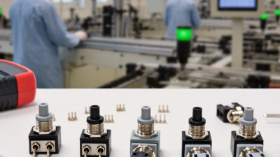
Choosing the right Micro Switch On Off begins with the application, not the product photo. A switch inside a control panel faces different demands than one beneath a foot pedal. Start by identifying the load type, voltage, current, mounting space, and expected operating frequency. A compact lever may fit neatly, yet its contact rating could be inadequate for a motor or heating element. That mistake is easy to make.
In practical equipment testing, I check the circuit conditions before comparing brands. Look for rated electrical life, mechanical life, terminal style, actuator force, travel distance, and protection against dust or moisture. The switch should also match the enclosure and wiring method. A datasheet from a recognized manufacturer is more dependable than a short marketplace description. Independent certification can add confidence, but it should never replace checking the actual ratings. Details matter.
There is no universal best switch. That answer feels unsatisfying, but it is accurate. A normally open contact may suit a start signal, while a normally closed contact may support a safety interlock. Confirm the contact arrangement with a meter before installation. It takes minutes.
Real-world conditions also deserve attention. Cold temperatures, vibration, repeated impacts, and side-loaded actuators can shorten service life. I have seen a switch fail because its lever was pressed at an angle, even though the electrical rating looked correct. Testing under the intended load is wise. A careful selection process reduces false starts, unexpected downtime, and unnecessary replacement costs. When uncertainty remains, consult the manufacturer’s technical documentation or a qualified electrical professional. Reliability starts with honest questions.

Choosing the right micro switch starts with its internal structure. A spring-loaded actuator moves a snap mechanism, changing the common terminal between normally open and normally closed contacts. The housing protects these parts, while the lever or plunger transfers movement from the machine. The click is useful feedback, but it does not prove electrical reliability.
Check the datasheet before choosing an on-off model. Compare rated voltage, current, inrush current, operating force, travel, and expected cycles. IEC 61058-1 provides safety requirements for switches used in electrical appliances. For dusty or damp locations, review the enclosure rating under IEC 60529. A 2024 market analysis by Allied Market Research estimates the global micro switch market could grow from about USD 1.2 billion in 2022 to USD 1.9 billion by 2032. That growth reflects wider use in appliances, vehicles, and industrial controls.
I usually match the actuator shape to the real motion first. A short plunger suits a direct press, while a hinged lever tolerates slight misalignment. Check the mounting hole spacing and terminal direction with a physical drawing. Small errors matter. A switch rated for ten amps may fail early when motor startup current is ignored. I have also seen a comfortable operating force chosen over contact protection, which was the wrong trade-off. Test repeated operation, temperature changes, and vibration before approval.
Choosing the right micro switch on off begins with the required switching specifications. Do not select one by size alone. A compact switch may fail quickly if its electrical rating is too low.
Write down the circuit voltage, current, and load type. Motors, solenoids, and lamps can create higher starting or inrush currents. For a simple control panel, a single-pole changeover contact may be enough. Other equipment may require normally open, normally closed, or both contact paths. Check whether the switch must break direct current or alternating current. These ratings are not interchangeable. Leave a safety margin above the measured load. It is a small habit with large consequences.
Mechanical details matter just as much. Measure the actuator travel, operating force, and release position beside the real mechanism. A roller lever may suit a sliding door, while a plunger can fit a narrow stop point. Confirm terminal style and mounting dimensions before ordering samples. Then test the switch under repeated operation, dust, vibration, and temperature changes. Real conditions expose weaknesses.
Do not trust one perfect bench test. Contact bounce, wiring errors, and uneven mounting can distort results. Review the expected electrical life and mechanical life separately. If the switch controls a safety-related function, use applicable professional standards and obtain qualified engineering review. A reliable choice is based on measured conditions, not a convenient guess.
Choosing a micro switch on/off begins with the actuator, not the catalog photograph. A 2024 MarketsandMarkets analysis projects steady growth in the micro switch market through 2029, driven by appliances, vehicles, and industrial controls. That growth reflects one practical truth: switching environments are becoming more varied.
Use a straight plunger when a rigid cam applies direct, repeatable force. It suits guarded panels and compact mechanisms. Choose a roller lever when a moving surface approaches sideways. The roller reduces sliding friction and helps tolerate alignment errors. A hinge lever needs less operating force, while a whisker actuator detects light contact from flexible parts. It is sensitive, but easy to damage.
Match the actuator to real conditions. In dusty equipment, select a sealed structure and prevent debris from reaching the contact area. In wet locations, check the stated ingress protection rating, not marketing language. For vibrating machinery, verify the release force and mounting stiffness. IEC 61058-1 requires safety-related switch tests, including endurance and abnormal-operation checks, but laboratory results cannot replace application testing. The electrical rating also needs careful review. A motor load can create a much higher inrush current than its running current. The switch may survive the first test, then fail after repeated cycling. That detail is often missed. I would test the complete mechanism at its highest temperature, fastest movement, and worst alignment. A smaller actuator may look efficient, yet its limited travel can cause unstable contact pressure. Reliability sometimes requires more clearance, not less.
How to Choose the Right Micro Switch On Off?
Evaluating Electrical Ratings, Durability, and Safety
A micro switch should match the circuit, not just fit the mounting hole. Check voltage, continuous current, and switching capacity in the datasheet. A 3-amp rating may apply only to a resistive load. Motors, solenoids, and lamps can create higher inrush current. That brief surge may weld contacts or shorten service life.
Measure the real circuit with a multimeter and, when possible, an inrush-current meter. Confirm whether the switch controls direct current or alternating current. Their contact behavior differs. Look for suitable insulation, dielectric strength, and creepage distance. The housing also matters. Dust, moisture, vibration, and heat can enter through a poorly protected installation.
Durability is more than a large cycle number. Check the mechanical and electrical life separately. A switch rated for one million mechanical operations may survive far fewer loaded cycles. Consider the actuator force, travel, and reset speed. I have seen designs fail because the actuator struck the switch too hard. Small details matter. Mounting alignment should prevent side loads and binding. Review the applicable safety standards for your region, and request test evidence from a qualified supplier. Do not rely on a familiar specification alone. Real installations are messier. A short bench test may also miss wear, arcing, or temperature rise. Recheck the choice under the harshest expected conditions.
How to Choose the Right Micro Switch On Off?
Selecting the best micro switch starts with the installation environment, not the catalog picture. Check voltage, current, load type, operating temperature, and required protection rating. A motor load can create a larger inrush current than its running current. That difference can damage contacts quickly. Confirm the electrical rating under the actual load. Do not rely on a headline value alone. Short travel matters. So does alignment.
For maintenance, inspect the lever, terminals, housing, and mounting screws during scheduled service. A loose switch may produce intermittent signals before total failure. The U.S. Department of Energy’s Operations & Maintenance Best Practices Guide reports potential maintenance-cost savings of about 8–12% through predictive maintenance compared with preventive methods. For micro switches, trend data can include actuation count, contact resistance, and failure location. Simple records help reveal repeated overloads. They also expose poor installation habits.
In field work, a clean-looking switch can still be the wrong choice. I have seen a low-force actuator installed against a rigid stop, causing early mechanical wear. The specification appeared suitable. The application was not. Choose an actuator that matches the cam profile, movement speed, and available clearance. Verify terminal insulation and enclosure sealing against the site conditions. IEC 60529 classifications help compare ingress protection, but they do not replace real inspection. Recheck the switch after initial cycling. Sometimes, the first selection needs revision.
| Selection Dimension | Option or Typical Range | Recommended Application | Installation and Maintenance Considerations |
|---|---|---|---|
| Contact Configuration |
SPDT: Common, Normally Open, and Normally Closed contacts SPST-NO: Normally Open contact only SPST-NC: Normally Closed contact only |
SPDT is suitable when one switch must provide both ON and OFF signal paths. SPST versions are suitable for simple single-circuit control. | Confirm the circuit logic before installation. A normally closed contact opens when the actuator is pressed, while a normally open contact closes when the actuator is pressed. |
| Electrical Rating | Common general-purpose ratings include 1 A to 15 A at 125–250 VAC. Low-current signal versions may be rated below 1 A. | Use a low-current model for control signals and a higher-rated model for direct switching of loads. | Select a switch with a voltage and current rating equal to or higher than the actual load. Motors, solenoids, and lamps may produce inrush or inductive current that exceeds their steady-state current. |
| Load Type | Resistive load, inductive load, motor load, lamp load, or electronic signal load | Resistive loads are generally the easiest to switch. For motors, relays, and solenoids, choose a switch specifically rated for inductive loads. | Do not use a resistive-load rating as the only reference for an inductive circuit. Consider a relay, suppression device, or suitable control module where required. |
| Operating Voltage |
Typical AC options: 125 VAC, 250 VAC Typical DC options: 12 VDC, 24 VDC, or other manufacturer-specified values |
Match the switch rating to the system voltage, including the highest expected operating voltage. | AC and DC ratings are not automatically interchangeable. Verify the exact voltage and current rating for the intended contact material and load type. |
| Actuator Style | Pin plunger, roller plunger, hinge lever, roller lever, or simulated roller lever | Pin plungers suit direct, centered movement. Roller actuators suit sliding, cam-driven, or angled movement. | Align the actuator with the moving part. Avoid side loading on a pin plunger and avoid excessive impact at the end of travel. |
| Operating Force | Common ranges are approximately 0.5 N to 5 N, depending on the switch design and actuator type. | Choose a low operating force for light mechanisms and a higher force where vibration resistance or positive actuation is needed. | The mechanism must reliably overcome the operating force without overstressing the actuator. Check both operating force and release force when precise movement is required. |
| Travel and Differential Movement | Operating travel is commonly around 0.3 mm to 3 mm. Overtravel is usually limited and must remain within the specified value. | Short-travel switches suit precise position detection. Longer-travel versions can tolerate greater mechanical movement. | Do not use the switch as a mechanical stop. Provide a separate stop or clearance so the actuator is not forced beyond its permissible overtravel. |
| Mechanical Life | Typical mechanical-life ratings range from 100,000 to 1,000,000 operations. Electrical life is usually lower and depends on the switched load. | Select a higher-life model for frequently cycled equipment, control panels, safety interlocks, and automated mechanisms. | Evaluate mechanical life and electrical life separately. Switching high current, inrush current, or inductive loads can shorten contact life. |
| Ingress Protection | Open-frame designs may have limited environmental protection. Sealed versions may provide ratings such as IP40, IP65, or IP67 when correctly installed. | Use an enclosed or sealed switch in areas exposed to dust, water spray, oil mist, or cleaning processes. | The final IP protection depends on the complete assembly, including terminals, cable entry, mounting surface, and enclosure. |
| Operating Temperature | Many general-purpose models operate approximately from -25°C to +85°C. Specialized models may support wider temperature ranges. | Select a temperature range covering the lowest storage temperature and the highest continuous operating temperature. | Temperature can affect contact resistance, actuator force, insulation performance, and sealing materials. |
| Terminal Type | Quick-connect tabs, solder terminals, screw terminals, wire leads, or PCB terminals | Quick-connect terminals support faster field replacement. Solder and PCB terminals suit compact assemblies. Wire leads suit sealed or remote installations. | Match the terminal type to the available wiring method and current requirement. Prevent loose connections, excessive bending, and strain on the terminal. |
| Contact Material | Contact materials may include silver alloys, gold-plated contacts, or other specified conductive materials. | Silver-based contacts are commonly used for general power switching. Gold-plated contacts are suitable for low-level signal circuits where stable contact performance is important. | Confirm that the contact material is appropriate for the current level, voltage, environment, and expected switching frequency. |
| Mounting Method | Screw mounting, snap-in mounting, panel mounting, or PCB mounting | Use screw mounting for serviceable equipment and PCB mounting for compact electronic assemblies. | Verify mounting-hole spacing, body dimensions, actuator position, and clearance before ordering a replacement. |
| Vibration and Shock | Performance varies by construction and application. Use the specified vibration and shock limits from the technical documentation. | Choose a robust, positively actuated design for machinery, transport equipment, and equipment exposed to vibration. | Secure the switch and wiring. Avoid mounting the switch where vibration can cause unintended contact movement or terminal fatigue. |
| On-Off Switching Frequency | Low-frequency manual operation, repeated automatic cycling, or high-frequency signal detection | Match the electrical and mechanical life rating to the expected number of cycles per hour, day, and service life. | Frequent switching of high-current or inductive loads accelerates contact wear. Use a relay or solid-state interface when the switch should only carry a control signal. |
| Replacement Compatibility | Check contact arrangement, terminal layout, body size, actuator height, mounting holes, electrical rating, and environmental rating. | A replacement should match both the electrical function and the mechanical interface. | Do not select a replacement based only on appearance. A similar-looking switch may have different terminal logic, travel, force, or load capacity. |
| Maintenance Inspection | Inspect actuator movement, mounting security, terminal condition, contact behavior, contamination, and enclosure sealing. | Periodic inspection is recommended for equipment subject to dust, moisture, vibration, high cycling, or safety-critical operation. | Disconnect power before inspection. Replace the switch if it shows intermittent operation, excessive contact resistance, physical damage, or unreliable actuation. |
| Best General Selection | SPDT configuration, suitable load rating, correct actuator style, adequate mechanical life, and environmental protection appropriate to the installation | A sealed roller-lever SPDT switch is often a practical choice for position detection in dusty or moving mechanisms, provided its ratings match the circuit. | The final selection must be verified against the equipment schematic, mechanical travel, load characteristics, ambient conditions, and applicable safety requirements. |