
An On Off On Rocker Switch has three positions: one ON position, a center OFF position, and a second ON position. The center detent often feels distinct beneath your thumb. In many designs, each ON position connects a different set of contacts, while the center position opens the circuit. That arrangement can select between two functions without using a separate toggle. But the label alone does not reveal exactly how a particular switch is wired.
This article explains the switch’s basic operation, common applications, terminal layouts, and key selection details. You’ll see why contact diagrams matter, and how electrical ratings, mounting dimensions, and maintained or momentary action affect suitability. For example, a panel switch might select between two lighting modes, but another model with the same appearance could use a different contact arrangement. Small differences matter. Check the manufacturer’s datasheet and wiring diagram before connecting anything, and isolate power during inspection or installation. A rocker’s printed markings are useful, but they are not a substitute for its specifications. That point can seem cautious, perhaps even overly so, until a wiring assumption proves wrong. By understanding the mechanism and verifying the details, you can choose and use an On Off On Rocker Switch with greater confidence.
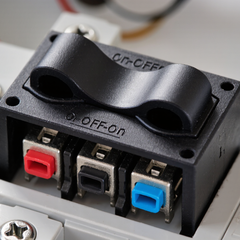
An on-off-on rocker switch has three selectable positions: ON, OFF, and ON. The middle position disconnects the switched output in many common layouts. Rock the actuator one way to select the first ON position, then the other way to select the second. The two ON positions may control separate outputs or route power along different paths. The switch’s internal contacts determine which arrangement applies.
Look at the terminal diagram before connecting anything. In some designs, a common terminal connects to one of two outputs, while the center position leaves both open. Terminal placement can vary, even when the rocker markings look familiar. Check the switch’s ratings against the circuit, and disconnect power before inspecting or wiring it.
A click is useful feedback, but it does not confirm the electrical state. That distinction matters. The rocker’s feel alone cannot tell you which terminals are connected; a continuity test, performed safely with the circuit unpowered, can help verify the layout.
An on-off-on rocker switch gives one common terminal two possible output paths. In one position, the common connects to the first output. In the center position, it connects to neither. Flip the rocker the other way, and the common connects to the second output.
That middle stop matters. It creates a genuine off state, rather than simply changing direction.
Inside, a moving contact bridges the common terminal to one of two fixed contacts. The switch does not normally connect both outputs at once, though the exact circuit depends on its design. A diagram may mark the terminals as COM, A, and B; other switches use numbers.
Terminal layout can be confusing, even on a small part. Check the manufacturer’s diagram, or use a continuity tester with power disconnected to confirm each position. Never rely on pin location alone.
An on-off-on rocker switch uses a pivoting actuator to move spring-loaded contacts between two powered positions, with a central off position. Inside, the key parts are the actuator, return mechanism, conductive contacts, insulating housing, and terminal tabs. The feel matters. A firm click usually signals a stable position, but it does not confirm the wiring.
Terminal layout depends on the number of poles. A common double-pole, double-throw design has six terminals: two commons and four switched outputs. In either end position, each common connects to one output; at center-off, both circuits are open. A single-pole version may have only three terminals. Check the molded diagram or use a continuity meter—terminal placement alone can mislead. IEC 61058-1:2016 covers appliance switches rated up to 480 volts and 63 amperes, but that scope is not a rating for every rocker switch. Use the marked voltage and current limits for the specific part. Small detail. Big consequence. A loose tab or mismatched load can cause heat, so verify the circuit is de-energized before inspection.
An on-off-on rocker switch has two active positions and a center-off position. It can direct power to one of two circuits, but its terminal layout is not universal. Read the switch’s wiring diagram before connecting anything. A label such as “common” or “load” matters more than the terminal’s physical position. Similar-looking switches may use different internal contacts. Check the rated voltage and current against the equipment, too.
Disconnect the power source before wiring, then verify that the circuit is dead with a suitable meter. Never rely on the switch being off. Follow the equipment diagram, use wire sized for the expected current, and protect the circuit with an appropriately rated fuse near the supply. Keep bare conductor out of view, tighten terminals securely, and use an enclosure that prevents accidental contact. For a vehicle or other vibrating setup, secure the wiring against rubbing and strain. It is easy to assume the center position always disconnects every terminal; that assumption deserves a check. If the diagram is unclear, stop and ask a qualified electrician rather than guessing.
An ON-OFF-ON rocker switch has three stable positions: one output, a center-off position, and a second output. In a typical SPDT design, the center terminal connects to either of two outputs, but not both at once. A DPDT version can switch two circuits together. Picture a small panel rocker: press one side for a forward circuit, leave it centered to stop, or press the other side for reverse. The exact wiring depends on the switch diagram, not its appearance.
These switches suit equipment needing two choices and a clear stop position, such as motor direction selection, lighting modes, or fan settings. An ON-ON rocker has two active positions and no center-off stop. An ON-OFF rocker has only one active position. The distinction matters: a center-off switch does not automatically make a circuit safe to service. IEC 61058-1:2016 covers appliance switches within a scope extending to 480 V and 63 A; individual switch ratings may be much lower, so check the marked rating and manufacturer’s wiring diagram.