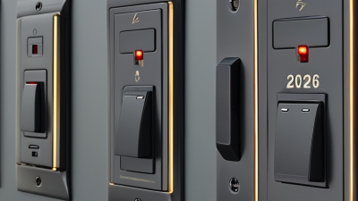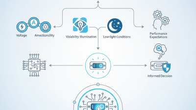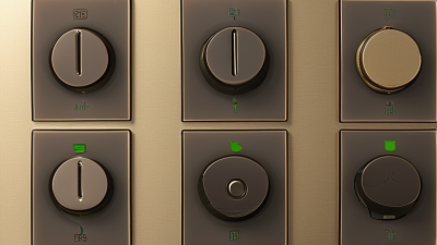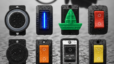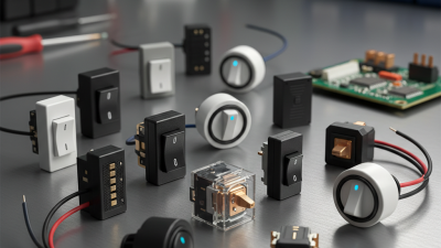
An Illuminated Rocker Switch combines simple switching with a visible status light. Its broad, gently curved actuator moves between two stable positions. Press one side, and the internal contacts change state. The built-in lamp or LED then shows whether the connected circuit is active. In a dark control panel, that small glow can prevent uncertainty and reduce accidental operation.
Understanding this device requires more than identifying its two positions. The switch may use an LED, neon lamp, or integrated resistor, depending on its voltage rating and design. Some models illuminate only when the load operates. Others contain a separate circuit, allowing the lamp to glow whenever power reaches the switch. These differences affect wiring, brightness, heat, and service life. Product markings matter. A switch rated for low-voltage direct current should not be treated like a mains-rated component.
A reliable explanation should connect theory with practical inspection. Look for terminal labels, current ratings, wiring diagrams, and the manufacturer’s approved application range. Notice the firm click, the lamp color, and any heat around the terminals. These details often reveal installation problems before failure occurs. Still, visual checks are not enough. Electrical testing should use suitable instruments and follow recognized safety procedures. Never assume a glowing indicator proves every connection is safe. That assumption can be wrong. This guide explores how an Illuminated Rocker Switch works, how its indicator circuit is arranged, and what users should consider when selecting or installing one. Practical experience helps, but careful verification remains essential.
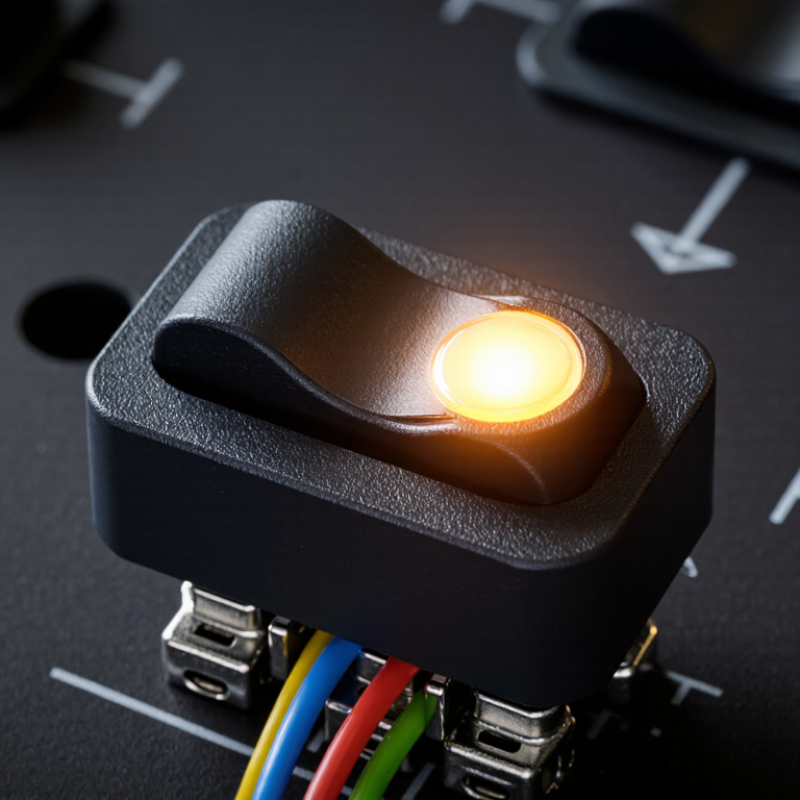
An illuminated rocker switch is a panel-mounted electrical switch with a built-in light. Its rocking actuator moves between two positions, usually on and off. The light shows the switch’s status or confirms that power reaches a selected circuit.
Inside the housing, metal contacts open or close when the rocker moves. A small lamp or LED sits beside, behind, or inside the actuator. Depending on the wiring, it may light when the switch is on, when power is available, or when the connected load is active. These functions can look similar, but they are electrically different. Always check the terminal diagram before installation.
The switch normally includes terminals for power, load, and ground or illumination. Some illuminated models need a separate neutral or ground connection. Others use only two terminals and illuminate through the connected circuit. This difference matters in vehicles, control panels, and household equipment.
A practical detail is easy to miss: the light may glow faintly when the circuit is off. Small leakage currents can cause this effect, especially with LED loads. It does not always mean the switch is defective. However, loose terminals, incorrect ratings, or heat around the housing require attention. The voltage and current ratings must match the application. Physical fit matters too. A switch can work electrically yet sit poorly in a thin panel. The description is not always intuitive, so a meter test and the manufacturer’s wiring diagram remain more reliable than appearance alone.
An illuminated rocker switch combines a manual actuator with a visible electrical indicator. Its outer rocker sits in a molded housing and pivots on small supports. Pressing one side moves an internal contact away or toward a fixed contact. A spring provides the snapping action users feel. Small parts matter.
Inside, the switch usually contains movable contacts, fixed terminals, a return spring, and an insulating barrier. The contacts carry the main load, while the indicator circuit uses an LED or miniature lamp. A resistor may limit LED current, especially in DC designs. Some illuminated switches connect the lamp across the switched load, while others use a separate terminal. The wiring arrangement is not always obvious from the front.
A technician can check the structure by identifying terminal markings and testing continuity with power isolated. When the rocker is off, the main contacts should normally show an open circuit. When pressed, they should close with low resistance. The indicator may need the correct polarity, voltage, or neutral connection. It may not light during a simple continuity test. That is easy to overlook.
A loose terminal can create heat and intermittent lighting. The housing should hold the rocker firmly, without excessive side movement. In real installations, diagrams sometimes simplify the internal circuit too much. Confirm the rated voltage, current, load type, and lamp connection before replacement. Never trust appearance alone.
Representative electrical values for a 12 V DC illuminated rocker switch
When the rocker is switched on, the internal contacts connect the supply to the load. A separate indicator branch uses a current-limiting resistor and LED, typically drawing about 2 mA. In this representative example, the LED operates at approximately 2 V, while the resistor drops the remaining 10 V from a 12 V supply. The contact voltage is kept low, approximately 0.3 V at 10 A, assuming a contact resistance of about 30 mΩ.
What Is an Illuminated Rocker Switch and How Does It Work?
An illuminated rocker switch combines a mechanical switch with a small indicator lamp. Pressing one side changes the internal contact position. You can feel a clear click.
Inside the housing, a spring mechanism moves a conductive contact between terminals. In a basic single-pole switch, the contact either completes or interrupts one circuit. The connected load may be a lamp, fan, heater, or control circuit. At the same time, an LED or neon lamp receives power through its own internal path. A resistor may limit current and protect the indicator.
The indicator’s behavior depends on the wiring. It may glow whenever power reaches the switch. It may also glow only when the load is active. Checking the terminal diagram matters. A bright light does not always prove that the load is working. I have found that loose terminals can create flickering, heat, or a weak click during practical testing.
Voltage compatibility is equally important. Some illuminated switches suit low-voltage direct-current systems, while others require alternating current. Using the wrong type can damage the lamp or create a serious electrical hazard. Before installation, I check the rated voltage, current, terminal layout, and panel thickness. The switch should fit firmly, with no exposed conductor near the housing. Its light is useful, but the contact system carries the real responsibility.
| Data Dimension | Description | Typical Value or Condition |
|---|---|---|
| Basic Definition | An illuminated rocker switch is a manually operated switch with a pivoting rocker actuator and an integrated light source. | The light indicates power availability, switch status, or circuit operation. |
| Rocker Actuator | The upper surface tilts around a central pivot when pressed. | One side commonly represents ON and the opposite side represents OFF. |
| Switching Mechanism | Internal contacts move between open and closed positions as the rocker is actuated. | A closed contact completes the circuit; an open contact interrupts it. |
| Light Source | The indicator is usually an LED or a small neon lamp built into the switch body. | LED indicators are common in low-voltage designs because they use little power and have long service life. |
| Indicator Wiring | The lamp may be wired across the switched circuit or between the supply and the switched output. | The wiring determines whether the light shows circuit power, an active load, or switch position. |
| Common Contact Form | Single-pole, single-throw designs use one input terminal and one output terminal. | SPST ON/OFF operation is widely used for simple lighting and equipment circuits. |
| Other Contact Forms | Some versions use SPDT or DPST contacts to select between circuits or switch two conductors. | The required contact form depends on the circuit layout and isolation requirements. |
| Typical Voltage Options | Illuminated rocker switches are manufactured for different AC and DC systems. | Common indicator voltages include 5 V DC, 12 V DC, 24 V DC, 120 V AC, and 230 V AC; the marked rating must be followed. |
| Typical Current Ratings | The contact rating specifies the maximum current the switch can safely interrupt under stated conditions. | Panel switches commonly range from low-current signal ratings to approximately 10–20 A, depending on voltage, load type, and construction. |
| ON-State Operation | Pressing the ON side moves the internal contacts together. | Current flows to the connected load, and the indicator illuminates when its wiring receives the required voltage. |
| OFF-State Operation | Pressing the OFF side separates the internal contacts. | The load circuit is interrupted; the indicator may turn off or remain on depending on the wiring arrangement. |
| LED Polarity | A standard LED conducts current in one direction. | DC versions may require correct positive and negative terminal orientation unless they include an internal rectifier. |
| Electrical Isolation | The switch contacts and indicator circuit may share terminals or use separate terminals. | The terminal diagram should be checked before installation, especially in mains-powered equipment. |
| Mounting Style | Most illuminated rocker switches are designed for panel mounting. | Rectangular snap-in cutouts are common, while the exact cutout size varies by switch series. |
| Environmental Protection | Some models include seals or protective covers to reduce exposure to dust and moisture. | An IP rating applies only when the complete switch and installation meet the specified test conditions. |
| Main Advantages | The switch combines circuit control and visual feedback in one compact component. | It improves usability in dark panels and helps operators identify an energized or active circuit. |
| Safety Consideration | Installation must match the voltage, current, load type, terminal arrangement, and applicable electrical requirements. | Disconnect power before wiring and use qualified personnel for hazardous-voltage circuits. |
An illuminated rocker switch combines a control mechanism with a small indicator lamp. The lamp shows whether a circuit is energized, selected, or ready for use. Common lamp choices include LED and neon, but their voltage and polarity requirements differ. An LED may need a resistor or internal current limiter, while a neon lamp usually suits AC applications.
The most common electrical configuration is SPST, which controls one circuit with one switching path. It works well for simple on/off loads. SPDT switches one common terminal between two outputs, supporting selection between separate circuits. DPST switches two conductors together, while DPDT manages two changeover circuits. These options suit equipment needing simultaneous switching or direction control.
Rocker switches may be maintained or momentary. A maintained type stays in position after pressing. A momentary type returns when released, often for testing or signal functions. Terminals can include power, load, neutral, ground, and lamp connections, depending on the design. Some indicators illuminate only when the load operates; others light whenever power reaches the switch. That difference is easy to miss.
Before installation, match the voltage, current rating, terminal diagram, and lamp polarity. AC and DC ratings are not interchangeable. Disconnect power and verify the circuit with suitable test equipment. A careful inspection also checks heat, loose terminals, and cramped wiring. Selecting by appearance alone is unreliable, and even experienced installers can overlook the indicator circuit.
What Is an Illuminated Rocker Switch and How Does It Work?
Applications, Benefits, and Selection Factors
An illuminated rocker switch combines switching control with a built-in light. When pressed, internal contacts open or close a circuit. A small lamp or LED glows when power reaches the selected circuit. This visual signal makes equipment status easier to read in dim areas. In practical testing, that detail matters.
These switches suit control panels, household equipment, vehicles, and compact machinery. In vehicles, illumination helps drivers locate controls without searching by touch. On control panels, it can show whether a fan, heater, or pump is operating. They also help reduce accidental operation during busy maintenance work. The benefit is immediate. However, bright illumination can cause glare in dark cabins. I have seen users choose appearance first and regret it later.
Selection should begin with voltage, current, and circuit type. Check the switch’s electrical rating before connecting a load. Then match the lamp voltage with the available power supply. Choose a sealed construction for dusty or damp environments. For frequent use, firm terminals and durable contacts are valuable. Confirm the mounting hole size and available rear clearance. No switch is perfect. A careful choice balances visibility, safety, workload, and installation space. Testing the switch under real operating conditions can reveal heat, glare, or loose connections that specifications may not show.