Choosing a Dpdt Rocker Switch in 2026 requires more than matching voltage and current ratings. The switch must fit the circuit, panel, environment, and operator’s habits. A DPDT device can control two independent circuits or reverse motor polarity. That flexibility makes it useful in control panels, marine equipment, test benches, and compact automation systems.
“Contact arrangement matters more than the rocker’s appearance,” says Michael Chen, a senior switch applications engineer. His point is practical. A switch may look rugged yet fail under vibration, moisture, or repeated switching. Check the schematic before comparing brands. Confirm the ON-ON or ON-OFF-ON function. Review terminal spacing, actuator shape, mounting-hole size, and wiring access. One overlooked measurement can force a costly panel redesign.
Electrical load deserves careful attention. Resistive loads and motor loads behave differently. Inrush current can exceed the normal operating current by several times. That detail is easy to miss. Look for an appropriate AC or DC rating, contact material, dielectric strength, and mechanical life. Sealed models suit dusty or damp locations, but sealing does not excuse poor installation. Consider temperature, gloves, visibility, and accidental activation. There is no universal best Dpdt Rocker Switch. The first choice may still be wrong after real-world testing. A short bench trial, clear labeling, and a final wiring inspection can reveal problems that specifications alone cannot show.
A DPDT rocker switch has two poles and two selectable throws. It controls two separate circuits at the same time. Inside, a tilting actuator moves conductive contacts between paired terminals. One position connects each common terminal to its first output. The opposite position connects them to the second output. This action can reverse motor polarity, select between signal paths, or control two independent loads.
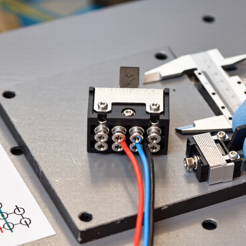
Many DPDT switches use six terminals in two rows. A continuity tester can reveal the exact layout before wiring. Never rely only on terminal appearance. During panel testing, I check the switch without power, then confirm each position with a meter. A maintained switch stays in its selected position. A momentary version returns when released. That small difference can change the whole control behavior.
Tips: Check the voltage and current ratings for the actual load, not just the supply. Motors and lamps may create higher starting or switching currents. Confirm the panel cutout, terminal type, contact material, and operating temperature. Leave enough space for wire bending. My checklist is useful, but not perfect; the datasheet remains the final reference. If the circuit carries inductive loads, add suitable suppression and verify the complete system under real operating conditions.
Identify the electrical requirements before comparing switch appearance or price. A DPDT rocker switch controls two independent circuits and offers two selectable positions. Confirm whether the circuit needs ON-ON, ON-OFF-ON, or momentary operation.
Check both voltage and current ratings, not just the advertised maximum. A motor, solenoid, or lamp may create a high startup surge. DC loads can also be harder to interrupt than resistive AC loads.
Leave a practical safety margin, especially in warm enclosures. A 10-amp rating may not suit a 10-amp motor.
Review the datasheet for resistive, inductive, and motor ratings. Confirm contact resistance, insulation rating, dielectric strength, and terminal temperature limits.
For low-voltage control signals, excessive contact resistance can cause unreliable readings. Verify the required circuit arrangement with a continuity meter before installation.
I have seen wiring diagrams interpreted from the actuator’s front view, causing reversed functions. That mistake is simple, but costly to troubleshoot.
Mechanical requirements deserve equal attention. Measure the panel cutout precisely, including width, height, and corner radius. Check panel thickness, mounting clips, terminal clearance, and wire-bending space behind the switch.
Select terminals that match the planned connector or wire method. Consider vibration, dust, moisture, operating temperature, and accidental impact.
An illuminated rocker may need extra wiring and panel depth. Protection ratings are useful only when the surrounding installation provides a compatible seal.
Recheck the fit with a paper template; drawings are sometimes clearer than memory.
Choosing a DPDT rocker switch in 2026 starts with its ratings, not its appearance. A DPDT switch controls two separate circuits and offers two possible connections for each pole. Check the voltage and current ratings for both AC and DC. DC loads can sustain arcs longer, especially with motors, solenoids, and LED drivers. A switch rated for 10 A resistive loads may perform poorly under motor inrush. Leave a practical safety margin.
I usually compare the load type, duty cycle, and terminal temperature before selecting a part. Measure twice. A DPDT ON-ON model suits forward-reverse control or circuit transfer. An ON-OFF-ON version adds a neutral center position, which can prevent accidental operation during maintenance. Some switches use momentary action instead of maintained positions. That difference matters when a machine must run only while the lever is held.
Inspect the pole and throw diagram carefully. Two poles do not always mean two fully independent circuits in every wiring arrangement. Confirm whether the center position disconnects both outputs. Then check terminal spacing, wire size, insulation, and panel cutout dimensions. I once focused on the electrical rating and overlooked the shallow rear clearance. The switch fitted, but the terminals pressed against the enclosure. A datasheet should confirm switching life, environmental limits, and contact material. If the application involves vibration, dust, or frequent switching, laboratory ratings may not match field conditions. Test the chosen configuration with the actual load before final installation.
Compare the switch architecture first, then confirm the electrical rating for your load. A DPDT switch controls two independent circuits and routes each pole to one of two outputs.
| Specification | Typical DPDT value | Selection guidance |
|---|---|---|
| Poles | 2 | Switches two separate circuits at the same time. |
| Throws | 2 per pole | Routes each common terminal to one of two output terminals. |
| Common terminal count | 2 | One common terminal is assigned to each pole. |
| Total terminals | 6 | Two common terminals plus four switched terminals. |
| Common switching positions | ON-ON or ON-OFF-ON | ON-ON provides two active positions; ON-OFF-ON adds a center-off position. |
| Contact rating | Varies by model | Match the voltage, AC/DC type, resistive or motor load, inrush current, and derating requirements. |
The chart shows the fixed structural characteristics of a DPDT rocker switch. Current and voltage ratings are not universal: generic specifications commonly list separate ratings such as 6 A at 125 VAC or lower DC ratings, so the exact datasheet must be checked before installation.
How to Choose a DPDT Rocker Switch in 2026?
A dependable DPDT rocker switch starts with its materials. Choose a housing made from heat-resistant nylon or polycarbonate for regular equipment use. Check the actuator surface for firmness and smooth movement. Contacts should resist oxidation and maintain low electrical resistance. Copper-based terminals can support efficient current transfer when properly plated. I once selected a switch by appearance alone. That decision caused a loose connection after repeated operation.
Terminals deserve practical attention. Quick-connect terminals simplify installation and replacement. Solder terminals suit compact assemblies but require careful heat control. Screw terminals allow adjustment, though vibration may loosen them without proper fastening. Confirm the terminal size, wire range, and rated current in the datasheet. Never assume a larger terminal means better performance. It may not fit the available wiring.
Mounting dimensions must match the panel precisely. Measure the cutout, panel thickness, and clearance behind the switch. A snap-in model works well on thin panels, while screw mounting offers stronger retention. Environmental protection also changes the selection. For dusty or damp locations, inspect the stated IP rating and sealing design. Check operating temperature, ultraviolet exposure, moisture, and vibration requirements. Ratings are not always tested under your exact conditions. A sample test under real load is wiser. My own checklist sometimes misses heat buildup near adjacent components, so I now inspect the entire panel after extended operation.
| Evaluation Dimension | Common Option or Specification | Typical Technical Data | Selection Guidance |
|---|---|---|---|
| Switch Function | DPDT, ON-ON | Two independent single-pole, double-throw circuits operated by one actuator; 6 terminals are normally required. | Choose ON-ON when the switch must transfer two circuits between two positions, such as reversing polarity or selecting between two signal paths. |
| Switch Function | DPDT, ON-OFF-ON | Two independent circuits with a center-off position; commonly uses 6 terminals. | Use this configuration when a neutral or disconnected center position is required. Confirm that the center position is electrically open rather than momentary. |
| Contact Arrangement | Maintained action | The actuator remains in the selected position until manually moved. | Suitable for power selection, motor direction control, lighting modes, and other functions that must remain active. |
| Contact Arrangement | Momentary action | The actuator returns to its normal position after release, usually by spring force. | Choose momentary operation for controls that should be active only while the rocker is being pressed. |
| Contact Material | Silver-based contact system | Commonly used for general-purpose switching because of good electrical conductivity and practical cost. | Suitable for many resistive and moderate inductive loads when the published voltage, current, and load-type ratings are not exceeded. |
| Contact Material | Gold-plated contact system | Provides low and stable contact resistance at low signal levels; plating thickness and base material affect durability. | Prefer for low-current or low-voltage signal circuits. Gold plating does not automatically make a switch suitable for high-power loads. |
| Actuator Material | Polyamide or thermoplastic rocker | Lightweight molded construction with good electrical insulation and impact resistance. | Appropriate for most indoor control panels. Verify the material's temperature rating and resistance to the intended chemicals. |
| Housing Material | Flame-retardant thermoplastic housing | Insulated housing typically designed to limit electrical tracking and reduce fire propagation. | Look for a documented flammability classification when the switch is installed in equipment with elevated fire-safety requirements. |
| Electrical Rating | Resistive load rating | Common panel-switch ratings range from low-voltage DC signal levels to approximately 10–20 A at 125/250 V AC, depending on construction. | Use only the exact rating specified for the selected switch. Do not infer the DC rating from the AC rating. |
| Electrical Rating | Motor, lamp, or capacitive load | Inrush current can be substantially higher than the steady-state current and can shorten contact life. | Select a switch with a published rating for the actual load type, or use a relay, contactor, snubber, or other suitable suppression method. |
| Voltage Compatibility | Low-voltage DC | Typical applications include control signals, battery systems, instrumentation, and embedded equipment. | Check minimum load capability if the circuit carries only a few milliamps, especially where oxidation or contamination may increase contact resistance. |
| Terminal Style | Quick-connect blade terminals | Common blade widths include 4.8 mm and 6.3 mm; the matching receptacle must have the same size and compatible thickness. | Choose when rapid assembly and service replacement are important. Use the correct fully insulated or partially insulated receptacles for the application. |
| Terminal Style | Solder terminals | Designed for direct wire attachment by soldering; terminal shape and soldering temperature limits vary. | Useful for compact wiring and low-volume assembly. Follow the specified soldering time and temperature to prevent heat damage. |
| Terminal Style | PCB terminals | Designed for through-hole or board-mounted assembly; pin spacing and footprint must match the PCB layout. | Choose only after checking the mechanical footprint, terminal orientation, board thickness, and required creepage and clearance distances. |
| Terminal Protection | Exposed terminals | Provides easy access for wiring but offers limited protection against accidental contact, dust, and moisture. | Best for enclosed equipment or protected control panels. Add barriers or insulation where conductive objects could bridge terminals. |
| Terminal Protection | Insulated or shrouded terminals | Reduces the chance of accidental short circuits and contact with energized conductors. | Prefer for higher-voltage installations, field wiring, and assemblies where terminal accessibility cannot be tightly controlled. |
| Panel Mounting | Snap-in mounting | Requires a panel cutout and suitable panel thickness; retention is provided by molded latches or clips. | Measure the cutout precisely and confirm the allowable panel thickness. A loose fit can reduce sealing and mechanical life. |
| Panel Mounting | Screw or threaded mounting | Uses a nut, screws, or a threaded bushing to secure the switch mechanically. | Choose for thicker panels, high-vibration equipment, or installations where service access and adjustable clamping are valuable. |
| Typical Cutout | Rectangular rocker cutout | Many compact rockers use cutouts around 19 × 13 mm or 30 × 22 mm, but dimensions are not standardized across all designs. | Use the manufacturer's dimensional drawing for the exact part; do not design the panel from a nominal switch family name alone. |
| Environmental Protection | Indoor, dry location | Basic non-sealed construction may be adequate when the switch is protected from water, condensation, dust, and corrosive agents. | Use an enclosure, gasket, or protective boot if the equipment may be exposed to cleaning fluids, condensation, or airborne contaminants. |
| Environmental Protection | Dust and splash resistance | Sealed versions may be specified with an IP code, such as IP54, IP65, or IP67, under defined test conditions. | Select the IP level according to the actual exposure. IP ratings apply to the complete installed assembly only when the required sealing method is used. |
| Environmental Protection | Water immersion or washdown | Higher ingress protection can limit dust entry and temporary water exposure, but ratings depend on test duration, pressure, and installation details. | Do not treat an IP rating as chemical resistance or permanent underwater approval. Verify the exact test conditions and application limits. |
| Operating Temperature | Standard industrial range | Many switches are specified around −20 °C to +85 °C, while actual limits vary with materials, sealing, load, and approval requirements. | Check both operating and storage limits, especially for outdoor equipment, engine compartments, refrigeration systems, and heated enclosures. |
| Vibration and Shock | General equipment use | Mechanical retention, terminal support, actuator design, and contact construction influence resistance to vibration and shock. | For mobile or vibrating equipment, use positive panel retention, strain relief, locking connectors, and a switch with documented vibration testing. |
| Creepage and Clearance | Separation between conductive parts | Required distances depend on working voltage, pollution level, insulation type, material group, and applicable safety standard. | Evaluate the complete switch and PCB or wiring layout together. A high voltage rating cannot compensate for inadequate system-level spacing. |
| Mechanical Life | Actuation endurance | Typical catalog values may range from approximately 10,000 to 100,000 cycles, depending on mechanism and test conditions. | Compare mechanical life with electrical life. Switching a rated load normally produces more contact wear than operating the actuator without a load. |
| Electrical Life | Load-dependent endurance | Electrical life is affected by voltage, current, inrush, power factor, switching frequency, arc suppression, and load type. | Use the published life curve or test condition that most closely matches the real application instead of relying only on the maximum cycle figure. |
| Actuator Design | Raised rocker | Easy to locate and operate by touch; usually provides clear visual position indication. | Suitable for frequent manual operation, but consider accidental actuation where the panel is crowded or exposed to contact. |
| Actuator Design | Guarded or recessed rocker | Reduces the likelihood of unintended operation and can improve protection against direct impact. | Prefer for safety-related modes, vehicle controls, industrial machinery, or equipment that may be handled roughly. |
| Visual Indication | Illuminated rocker | May use an LED or lamp and can require a separate voltage rating, polarity consideration, and additional terminals. | Confirm whether the light is internally connected or separately wired, and verify current consumption and compatibility with AC or DC power. |
| Compliance Documentation | Safety and material documentation | Relevant records may include electrical test reports, flammability information, environmental test data, and restricted-substance declarations. | For regulated equipment, keep the datasheet, dimensional drawing, ratings, and revision-controlled approval documents with the design record. |
| Best Overall Selection | Application-matched DPDT rocker switch | Correct circuit function, load rating, terminal style, panel fit, operating temperature, sealing level, and service life. | Select the smallest specification that safely exceeds the real electrical and environmental requirements without relying on brand names or nominal ratings alone. |

When choosing a DPDT rocker switch in 2026, start with the circuit, not its appearance. A DPDT switch controls two circuits and offers two operating positions. Confirm whether the circuit needs maintained or momentary action. Check the rated voltage and current for both AC and DC loads. Motors, lamps, and heating elements can create different switching demands. A switch that handles a resistive load may fail early with a motor.
Read the technical datasheet carefully. Verify terminal layout, contact arrangement, panel cutout size, actuator dimensions, and operating temperature. Check whether the enclosure needs an IP rating for dust or moisture protection. Safety documentation should identify applicable requirements, such as IEC 61058-1 or regional UL and CSA standards. Certification marks are useful, but they should match the actual model. Do not rely on a similar-looking part.
Installation details matter just as much. Disconnect all power before wiring, including stored energy from capacitors. Use the correct wire size, insulation rating, fuse protection, and secure crimp terminals. Leave enough space behind the panel for bending wires without stressing the terminals. Test continuity in every switch position before energizing the circuit. Then test the real load under controlled conditions.
Small errors become expensive.
In practical panel work, terminal numbering can be surprisingly confusing. I once assumed two identical layouts were interchangeable; they were not. A quick diagram and meter check would have prevented that mistake. Recheck the datasheet when anything feels uncertain.